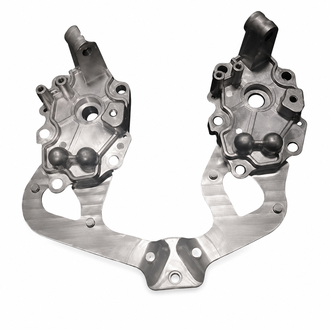
Most of the cost of a die-cast part is decided before the die is cut. Wall thickness, draft, radii and where the parting line sits are all fixed on the drawing - and every one of them has a process consequence that shows up later as porosity, distortion, a stuck part or an extra machining operation.
This guide sets out the design rules that matter for zinc and aluminum alloy die casting, written for buyers and product designers who need to know which changes are cheap at the drawing stage and expensive after tooling.
1. Why design for manufacturing comes before the drawing is frozen
Die casting is a process where metal is injected into a steel die at high speed and pressure, then solidifies. The die determines the shape; the process determines what happens to the metal as it fills and cools. A design that ignores either one cannot be fixed by tighter process control.
The practical rule for a custom part: hold a DFM review before the die is ordered, not after the first sample. Changes at the drawing stage cost engineering time; changes after the die exists cost welding, re-machining or a new die.
2. Wall thickness
- Keep walls as uniform as possible. Thick sections cool more slowly than thin ones, and the shrinkage difference is what produces internal porosity, sink marks and warping.
- Avoid isolated thick masses. Where a thick section is structurally necessary, core it out or replace it with ribs.
- Minimum wall depends on the alloy and the part size. Zinc alloys flow better and allow thinner walls than aluminum, which is why small precision parts are often zinc. Confirm the minimum with the foundry for your specific geometry.
- Thickness affects weight, cycle time and cost. A reduction of a few tenths of a millimeter across a part can show up clearly in unit price, provided the part still meets its strength requirement.
3. Draft angle and parting line
- Draft is what lets the part come out of the die. Typical practice is around 1 degree on internal and external walls, more on textured surfaces and on deep cavities.
- Textured surfaces need extra draft. A heavily textured wall requires a larger angle, because the texture itself resists ejection. This is a design decision, not a finishing detail.
- The parting line should sit where a visible line is acceptable, ideally on a corner, edge or hidden face.
- Draft direction matters for appearance. The side that forms the visible surface of the finished product should be drafted so that polishing or texturing is straightforward.
4. Radii and fillets
- Sharp external corners interrupt metal flow and concentrate stress; add radii wherever the design allows.
- Internal corners should be radiused too, ideally with a fillet comparable to the wall thickness.
- Radii also improve die life, because sharp corners are where the die erodes first.
5. Ribs and bosses
- Ribs add stiffness without adding mass. Keep rib thickness below the nominal wall so the rib cools at a similar rate to the surface it supports.
- Bosses should be cored, not solid, and should be tied to a wall or rib rather than standing alone.
- Boss height and diameter matter for both casting and the fastener: a boss that is too tall relative to its diameter fills poorly; one that is too thin can crack when a self-tapping screw is driven.
6. Holes and threads
- Small, deep cored holes are difficult: the core pin bends or breaks. The smaller the hole, the shorter it must be relative to its diameter.
- Threads are usually cut or formed by a secondary machining operation rather than cast, because cast threads cannot hold the tolerance or strength required.
- Cored holes are still valuable - they reduce machining stock and drilling time - but they should be designed to the process, not to the thread specification.
7. Undercuts and slides
An undercut - a feature that blocks the part from coming straight out of the die - requires a slide or a loose insert. That adds tooling cost, adds cycle time, increases maintenance and is another thing that can fail in production. Two questions are worth asking at the design stage:
- Can the feature be redesigned so the part ejects in a straight line?
- If it cannot, is the feature worth the tooling cost and the production risk?
8. Ejector pins and gate marks
Every die leaves marks: the ejector pins that push the part out, and the gate where metal entered. These are normal, not defects, and they should be planned rather than discovered.
- Tell the toolmaker which surfaces will be visible in the finished product, so ejector pins and the gate can be placed on hidden faces.
- Decide the gate position early, because it influences filling, weld lines and where machining may be needed afterwards.
- If a surface must be completely mark-free, that requirement belongs in the tooling discussion and may change the die design.
9. Tolerances that die casting can hold
- General dimensional tolerances are achievable across the part, but they are wider than machined tolerances and depend on part size.
- Tolerances across the parting line are looser than within one die half, because two halves move relative to each other.
- Where a tight tolerance is essential - a bearing seat, a sealing face, a mating surface - plan a machining allowance and specify the final tolerance after machining.
- Adding a machining allowance is cheap; discovering after the first sample that it was needed is not.
10. DFM review checklist
- Wall thickness as uniform as the function allows, no isolated thick masses.
- Draft angle specified on every wall, larger where the surface is textured.
- Parting line placed on an acceptable face, agreed with the toolmaker.
- Radii on internal and external corners.
- Ribs thinner than the nominal wall; bosses cored and supported.
- Cored holes within the process limits, threads assigned to machining.
- Undercuts minimised, and any slide justified in cost terms.
- Ejector and gate locations agreed against the visible surfaces of the product.
- Tight tolerances identified and assigned to machining, with allowance built into the casting.
- Material and finish agreed, since both change the casting requirement.
Dongguan Jiudian Precision Metal Industry Co., Ltd. produces custom zinc alloy and aluminum alloy die casting parts for consumer electronics, automotive, telecommunications and new energy applications, and builds the dies in-house. Send us your drawing or sample and we will return a DFM review together with tooling and unit-cost feedback.